
Ever since hearing about Rob Miles' Bitshift Variations in C Minor, a 4-voice polyphonic 16 minute piece of algorithmically generated music, I wanted to implement it in hardware. Getting it onto just any microcontroller seemed too easy, so I wanted it to run on the smallest µC I could find — the ATtiny4. A while later, I ported the program onto the infamous Three Cent Microcontroller, the Padauk PMS150c.
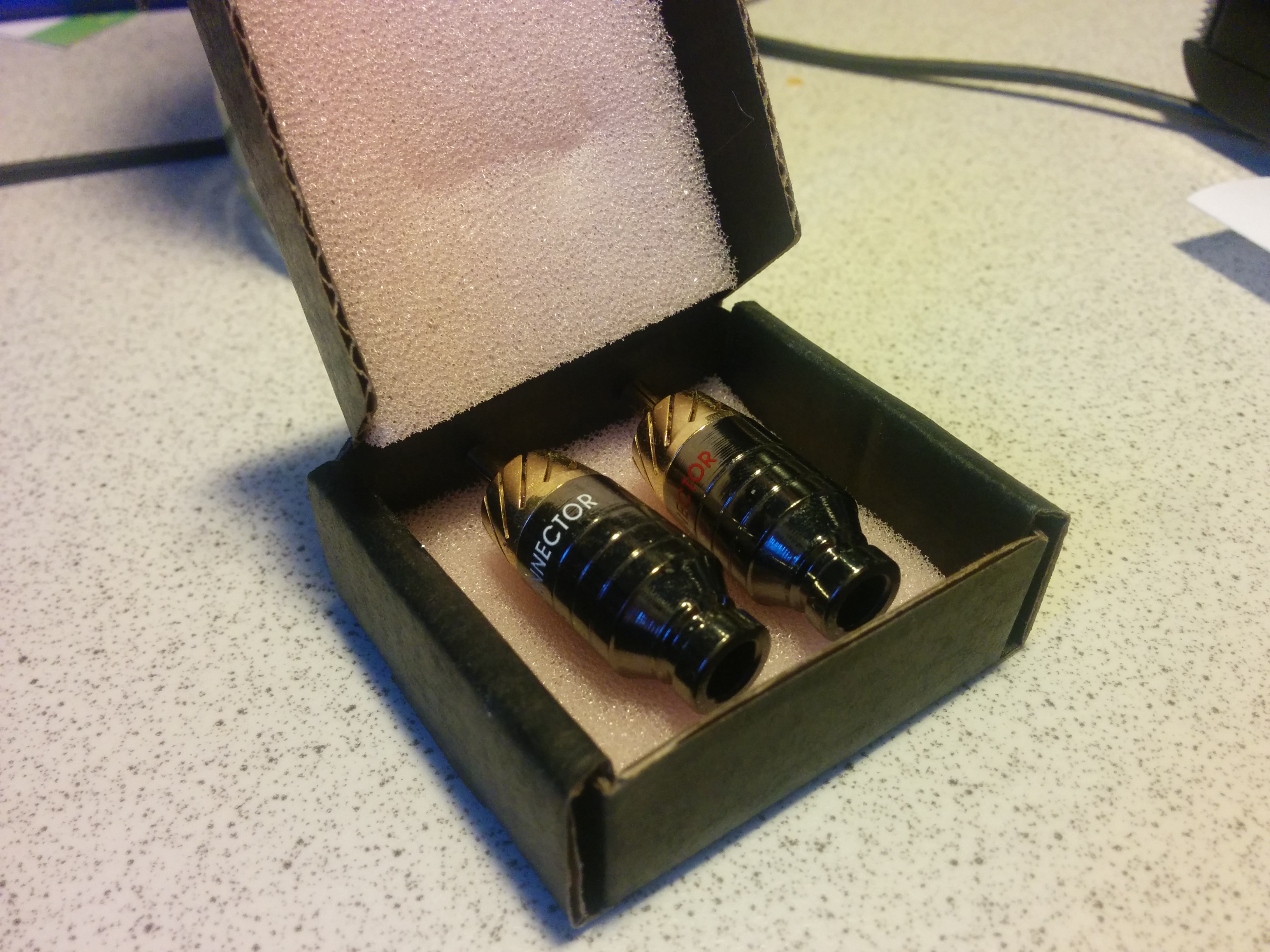
Oh, and it's completely self contained inside an RCA jack – and detects when it gets plugged in.
Video Demonstration of the device playing
Slides of the lightning talk given at 35c3
ATtiny and Padauk git repositories
At the high level, there are two functions: Primarily, playing the music, and secondarily checking whether the device is (still) plugged in to conserve power while it isn't.
The ATtiny has a pretty powerful timer/counter unit, and it does double-duty by generating both the PWM signal used for audio output, as well as an interrupt to trigger generating the next PCM sample.
Precisely, we set it to its 8-bit, non-inverted fast PWM mode, with no prescaler, and also enable the overflow interrupt. This means, the timer counts up from zero to 255 using the same 4MHz clock as the CPU core, the PWM output is high from zero to whatever its duty cycle should be, and when it reaches TOP, it resets to zero and raises the overflow interrupt.
Some quick maths: The fastest the MCU can run at when powered by the 3V from the coin cell is 4MHz. Those 4MHz divided by the 256 steps gives us a PWM base frequency of 15.625kHz. By calibrating the internal oscillator a bit high, we can easily get this to a round 16kHz. Since the original tune has a sample rate of only 8kHz, we only need to generate a new sample every two overflows/interrupts. This turned out quite handy, since sample generation in the end turned out to take a bit over 400 cycles.
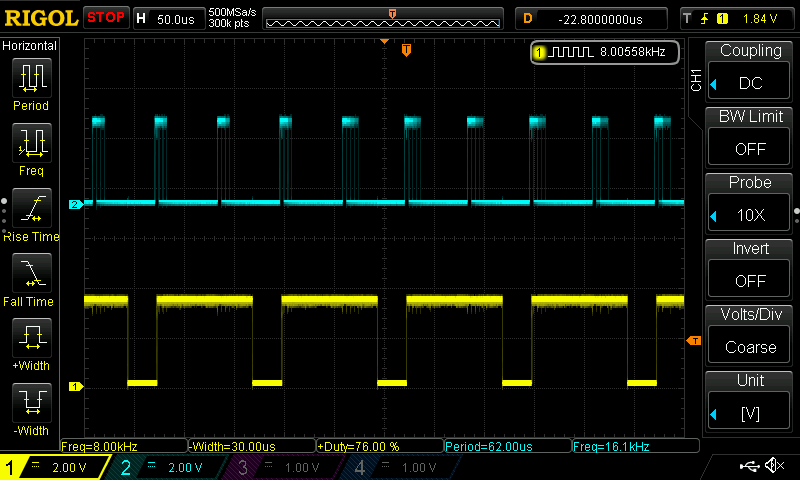
 In the graph above, I've plotted the counter, its compare-against value, the resulting PWM output, as well as the overflow interrupt, and the execution/duty cycle of the
 sample routine, triggered by the overflow interrupt.
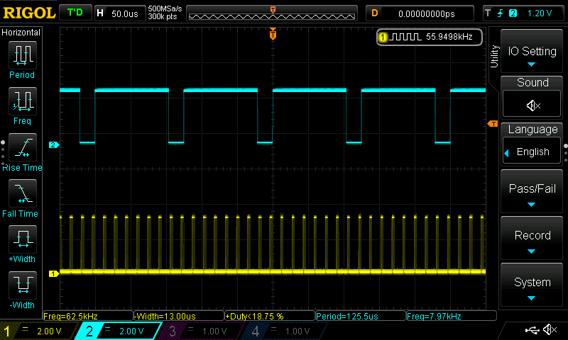
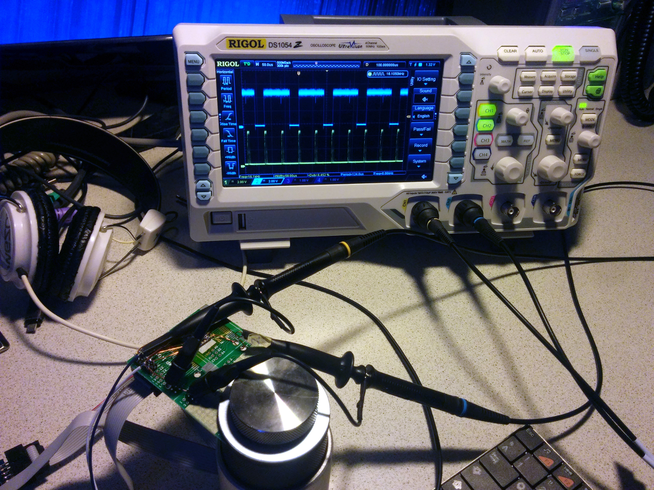
And below you can see the duty cycle and PWM output on the real chip; the "two samples per interrupt" thing is clearly visible. (And this duty cycle/debug output turned out handy later too, to calibrate the oscillator by observing the frequency on my Rigʟol 'scope)
When thinking about the mechanical design aspect, I came to the conclusion that I couldn't fit a physical button (let alone a latching switch) into the enclosure to turn on or off the music. So the idea to automagically detect, when the thing is plugged in or not came to mind. In theory, this is very straight forward: When it is plugged into an audio sink, there is an electrical connection from the audio output to ground. All we need to do is to regularly assert a high signal on the centre contact of the RCA jack and checking whether it gets pulled low.
On the software side, we keep track of where in the piece of music we are, and enter Power-Down Mode , which disables the timer/counter and even the main clock. During this state, we wait for a low level (in the zero volts sense) external interrupt, that will be triggered when the device is plugged in, at which point we restart playing.
In practise, it's slightly more complicated: The typical impedance of a line-level audio input is 20k-100kΩ, way higher than the internal pull-ups of the ATtiny, but easily solved with an external one. Also, the pin change interrupt functionality isn't available on the PWM output pin, but that's again easily worked around by just shorting those two together.
According to the datasheet, power consumption in this state is below 0.15µV; about the same as the cell's self-discharge rate, so this will (*knocks on wood*) keep the battery alive for years.
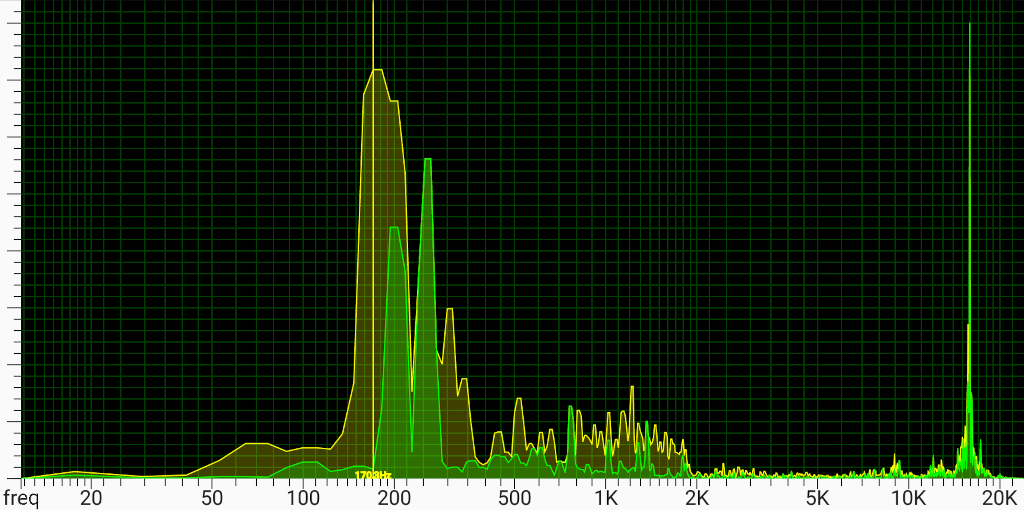
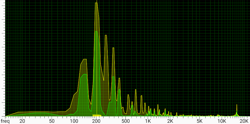
There is one downside of using a 16kHz PWM base frequency: Its audible. I originally intended to just ignore it, but a friend rightfully convinced me to add a low pass RC filter.
A quick and dirty spectrum analysis captured with my phone confirmed that this is indeed the source of the noise. I decided the cut-off frequency and response curve rather arbitrarily (by looking at my box of SMD components) at about 8kHz, but it does the job well enough, so I stuck with it when ordering the final BOM.
With the theory out of the way, all that's left is to churn out the code. I decided to manually transcribe Rob's C program into AVR assembly; partly for fun, partly as a (premature?) optimisation strategy. The ATtiny doesn't have hardware mul/div/mod, and I only needed a few right-hand multiplicands/divisors, so I wrote some extremely bespoke, hand-optimized variants for that.
I started by keeping the C program intact, and first simplifying it, then later replacing each operation with a C macro that implemented the corresponding machine code instruction. After each miniscule change, I generated a PCM stream and diff(1)ed it against a known-good sample to avoid introducing errors. Each such change was automatically committed; resulting in 136 commits titled new version, before finally adding the initialization code and running it on the real MCU.
At this point unbeknownst to me, I made a mistake when writing one of the fakeASM macros:
I inverted a branch condition in mod3, so it jumped when it shouldn't and didn't when it should.
This caused voices 3 and 4 to be completely unrecognizable on the actual MCU.
I would only find the cause of this bug when returning to the project over a year later, after the great simavr finally got rudimentary support for the ATtiny10 family. Once I fired up gdb(1), the problem became obvious immediately, and the patch is a single machine code instruction. m(
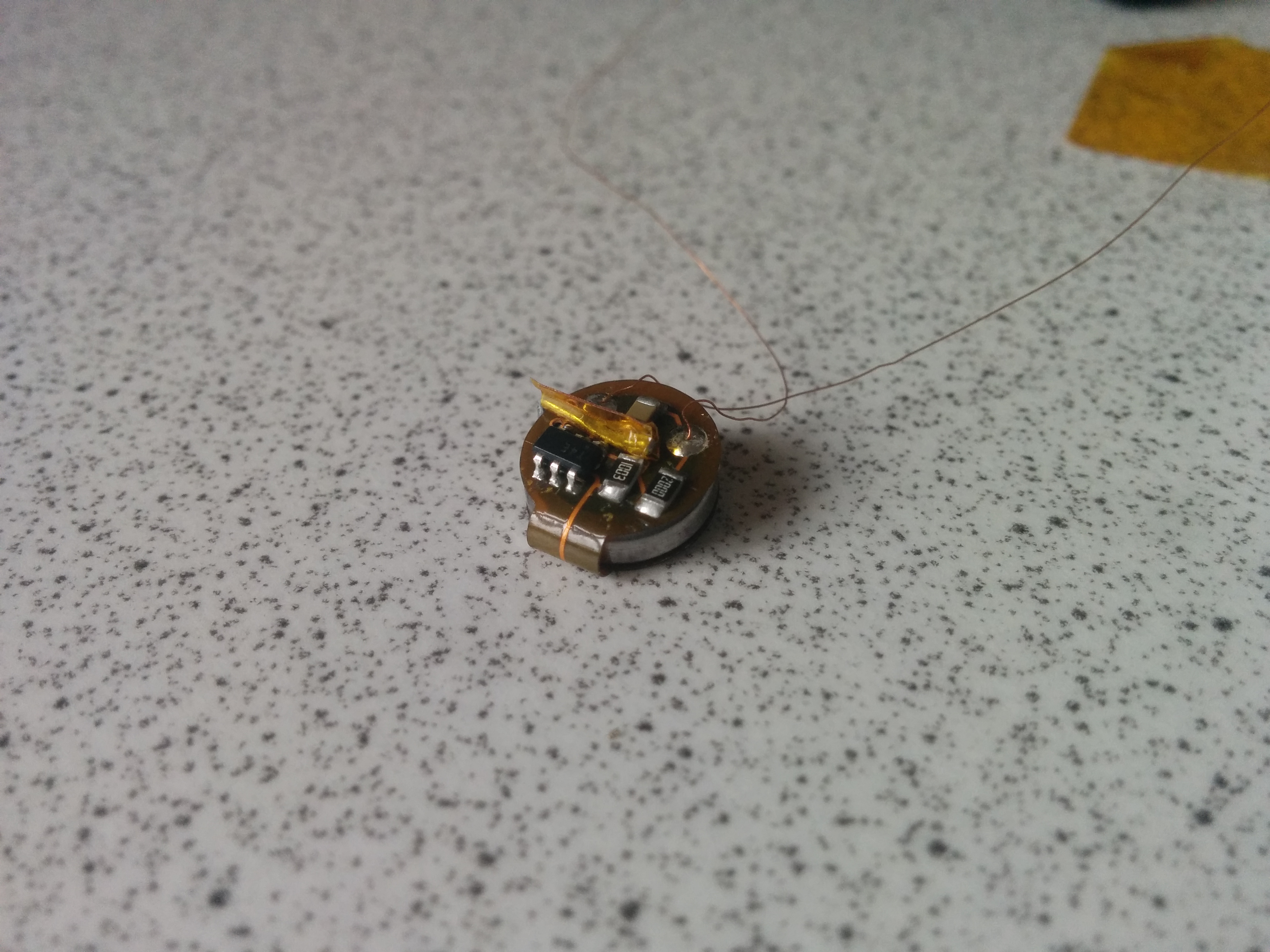
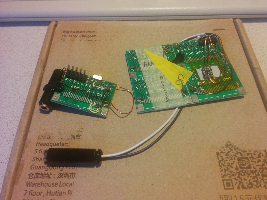
Initially, I tried point-to-point wiring with enameled wire. That failed miserably: The solder wouldn't wet on the battery, the alternative—silver conductive glue—was messy and didn't appear strong, and everything just flopped around. After multiple layers of kapton tape to isolate the battery and components, the whole thing also became too large to fit the enclosure.
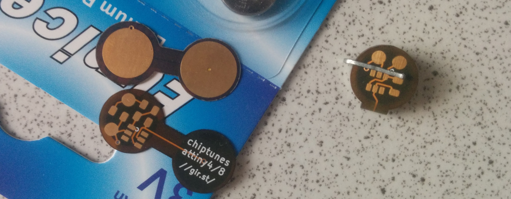
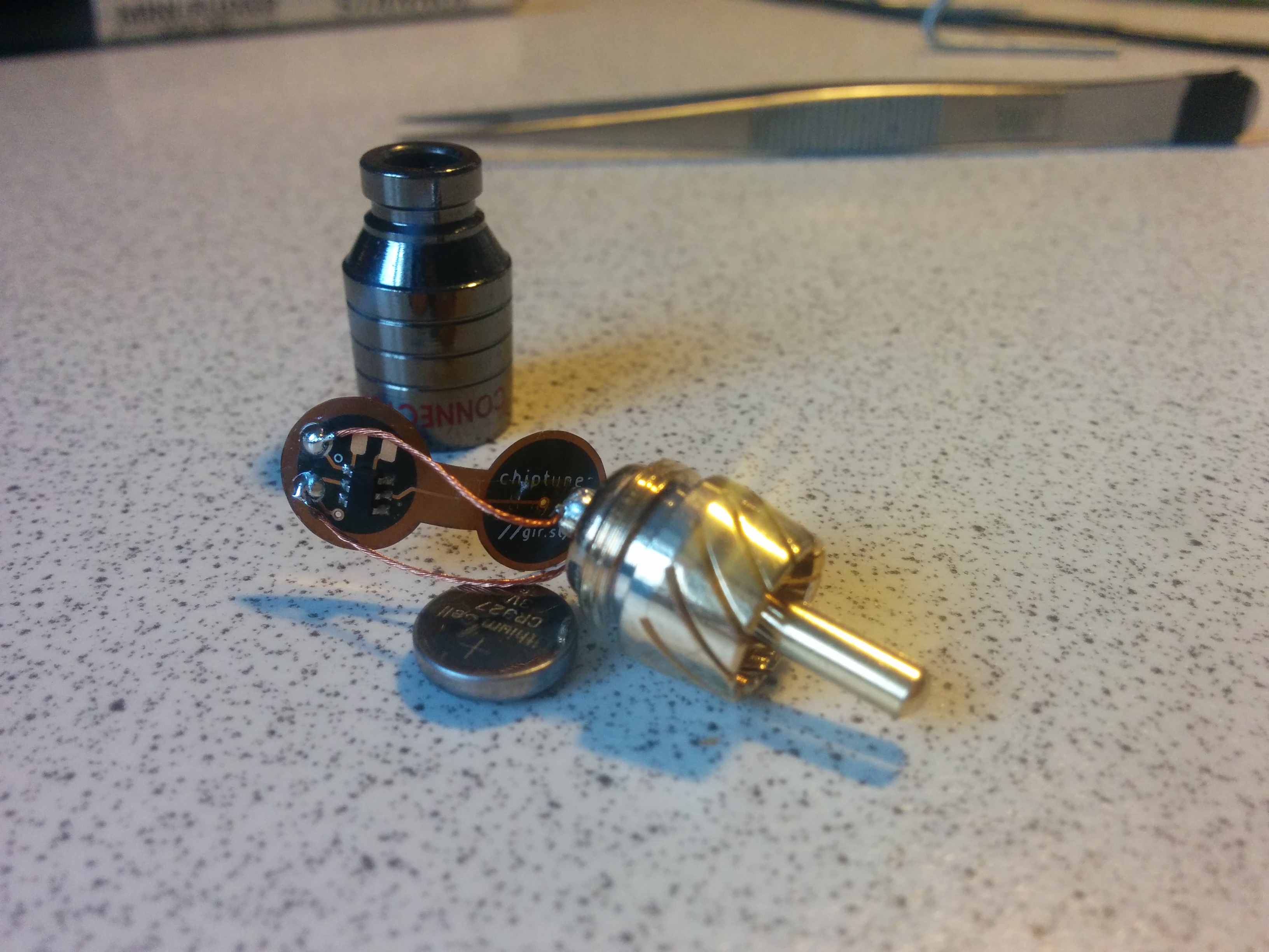
A flexible PCB (yes, that's available for us fucking hobbyists now! right?! i know!) solved all those problems at once. I designed the board to wrap around the coin cell; with battery contacts on the inside and the components on the outside. A clip made from a paper staple puts pressure on the sandwich to keep the thing powered. The PCB itself also keeps the cell insulated (requiring only a single strip of tape around the rim) and everything rigid.
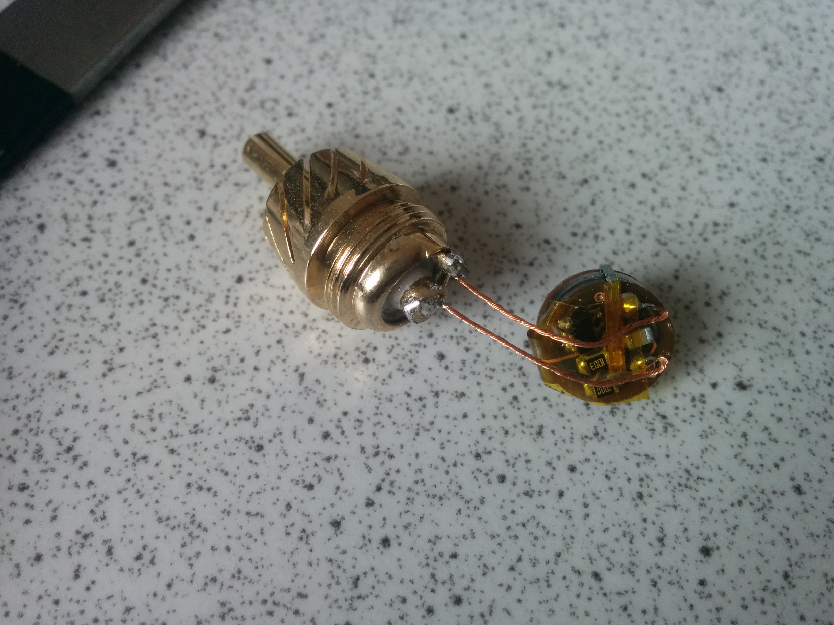
Two wires from the PCB to the solder points on the inside of the RCA connector were still required. This was quite the head-scratcher: It took me a while to find a way to screw together the plug housing without twisting off the wires. The solution turned out to stuff the PCB as far back up in the shell and lightly twisting the wires together counter-clockwise, so they would untangle when the plug housing was closed.

Using the ATtiny always felt a bit like a cheat: it has comparatively generous peripherals and a huge number of very flexible registers (16) that can be directly manipulated. And I had this home-built programmer lying around, for Padauk's microcontrollers I got from someone on the EEVBlog Forums. And about 500 of the PMS150Cs.
The PMS150c has gotten a little bit of fame for costing only 3.something US-cents per piece, in relatively low quantities. For its price, it's very featureful: 1024 words of (one-time-programmable) program ROM, 64 bytes of SRAM, an 8 bit PWM-capable timer, a (little strange) 16 bit timer, internal comparator and voltage reference. According to some, Padauk's instruction set is heavily inspired by older PICs, with most operations taking place on a single accumulator register. On the downside, the manufacturer hasn't released much documentation: the datasheet omits how assembler mnemonics map to actual ones and zeros, and expects you to use their proprietary (and Windows-only) IDE, programmer and in-circuit emulator. That IDE doesn't even have a C compiler; it uses a strange language they call "mini-C": essentially, an assembler with some syntactic sugar borrowed from C.
A talented group of hobbyists, with js_12345678_55AA, tim_ (cpldcpu) and spth (pkk) leading the way, have despite this lack of upstream support created an impressive and fully open source C toolchain, including a compiler, assembler, linker, disassembler, simulator, programmer hard- and software and low-level documentation.
Porting Chiptunes to the PMS150c required a complete re-translation of the original C code into assembler, to make best use of the tight cycle requirements (which I just barely stayed within: 507 of 512 availably cycles used worst-case). After burning five ICs with some test programs, to figure out how to initialize the various peripherals, it only took another two additional chips to get the full program debugged. That's seven chips, but a fair amount of tries more than that: You can actually program OTP memory multiple times, as long as you are only changing 1s into 0s. So I left some space below the reset and interrupt vectors, appended a new version of the code, and fixed up the GOTOs by replacing them with NOPs and adding a new jump right after it. I swear, I'm not that cheap, but fiddling with the ZIF socket each time was more time-consuming than this workaround.
ATtiny Padauk
g:	ANDI	t, 0x07
	MOV	tmp, i2
	ANDI	tmp, 3
	CPSE	tmp, zero
	SUBI	t, -8

	LDI	Xlo, lo8(notes)
	ADD	Xlo, t
	LD	t, X
g:	AND	a, #0x7
	MOV	notes_ix, a
	MOV	a, i2
	AND	a, #3
	T0SN	f, z
	GOTO	skip_plus8
	MOV	a, #8
	ADD	notes_ix, a
	skip_plus8:
	IDXM	a, notes_ix
The Padauk-Chiptunes version has some minor differences compared to the ATtiny one: Firstly, I'm using both timers, which allows me to use a higher PWM base frequency (64kHz) and avoid the low-pass filter. Secondly, the Padauk's internal pull-ups are high enough to not require an external one. This means, the goal of 0 external components is finally reached!
I did encounter some challenges, though: The t1sn M.n (test for a high bit in SRAM memory and skip next instruction) and set1 M.n (set bit in SRAM memory cell) only work on the first 16 addresses; something not clearly pointed out in the datasheet (I only noticed it because the reverse engineered instruction set documentation had a 4-bit-wide address field). The ucsim microcontroller simulator had some bugs regarding these (and similar) instructions, throwing me off the right track for a bit (I submitted patches to upstream). There were also some strange behaviours of the timer16-interrupt and sleep modes, and JS helped me work around them. But other than that, it was pretty smooth sailing; only made possible due to the high quality of work of the aforementioned individuals.
I didn't bother creating new PCBs; I had some left over ones without the low-pass filter, and left the external pull-up unpopulated.
DoJoe's Noiseplug should not be unmentioned. The project is similar in vein and I stumbled upon it while researching some detail about the ATtiny.
I built myself a development board out of an adapter PCB, since the pitch of the pads fit (one side of) the SOT23-6 form factor exactly. The other side was then connected by wires. Another (earlier) iteration of the devboard used a miniscule ATtiny adapterboard I glued on a whole panel of the adapter PCBs to make it larger. The latter of those I took to 35C3.
I ordered the flex PCBs from OSHPark.com (no affiliation) for roughly one USD per board. Turn-around time was faster than expected, but some of them had etching defects.
My attempt to port the program to the PIC10 series failed: The assembler language is very limited, causing me to go over the 512 instruction cycles per sample. Having had no experience with the PIC ecosystem (in large part due to its IMO inferior toolchain (e.g. no Free C compiler)), I assumed I could increase the clock speed to match, but since each instruction takes four clock cycles, that exceeds the limits of the built in oscillator. Given that I'm pretty happy with the Padauk version, I just cut my losses (two-ish weekends of time, plus 60ish€ for parts).