hardpass is an open source hardware password manager. Its motto is "Never roll your own crypto" - use gpg instead!
The project is documented on hackaday.io, GitHub and iSticktoIt.net.
2018-03-30: added pictures of the pcb
Note: Documentation on the software is not yet finished.
gpg2 to keep your data safe and the pass scheme to keep your data accessible
A big part in the development of hardpass was the focus on not just a completely Libre end product, but also make the toochain as Open as possible.
The circuit board was developed with KiCad, some 3d models were made in FreeCAD, and the software for this project thing can be built on a Linux / GNU/Linux distribution with the GNU GCC compiler.
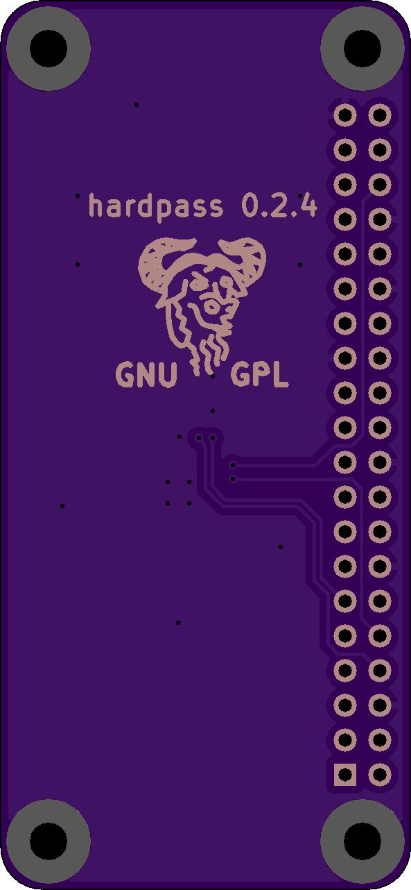
As a logical consequence, I have licensed the parts of hardpass that I own (i.e. excluding libraries, some footprints and 3d models, etc.) under the GNU General Public License, Version 3, with some minor parts under the Creative Commons Attribution & Share Alike 4.0 International. This allows anyone to recreate this project, and is an encouragement to to contribute you improvements back to the community.
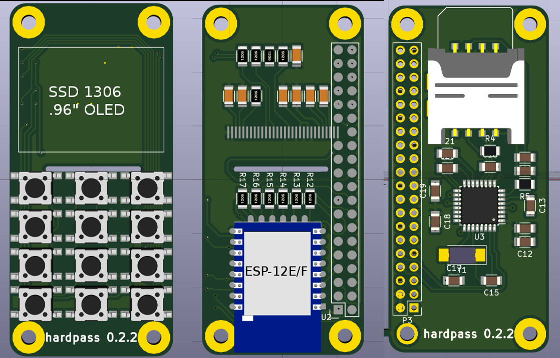
Version 0.1, the initial prototype, used only easily obtainable modules (ESP-03, SSD1306 OLED module, 6mm tact. buttons), mounted on the front and back of the Raspberry Pi Zero. It is (for the exception of the smart card interface) 100% compatible; so if you don't want to solder small components and/or get a PCB manufactured, this is still an option.
Since Version 0.2 a PCB has been designed, which houses the display, PIN pad and WiFi module. A secondary PCB is currently in the design phase which will hold a TDA8029 Smart Card interface and SIM card tray.
Version 0.2.0 was attempting to use the 20 pin variety of the SSD1306, but had to be abandoned due to availability and solderability issues. Version 0.2.1 was the first built prototype, replacing the OLED circuitry with header pins for a preassembled module to speed up development. The current version, 0.2.2, made the switch to the 30 pin screen, and with the same version number, hardpass-SCI was introduced.
The device is supposed to be as modular as possible, so parts of the software (e.g. User Interface) or hardware (e.g. swap ESP8266 for a Pi Zero W).
You don't need a lot of tools to build you own hardpass. A soldering iron with a fine and a flat tip, a pair of tweezers, some tape and a steady hand should suffice.
Below is the Bill Of Materials, which you should obtain fully before continuing.
Most of the parts can be obtained from AliExpress rather cheaply. Some parts (see footnotes) have to be ordered from some where else. The APX803 and its resistor can be replaced by an RC circuit. **TODO**: find suitable values for RC-reset!
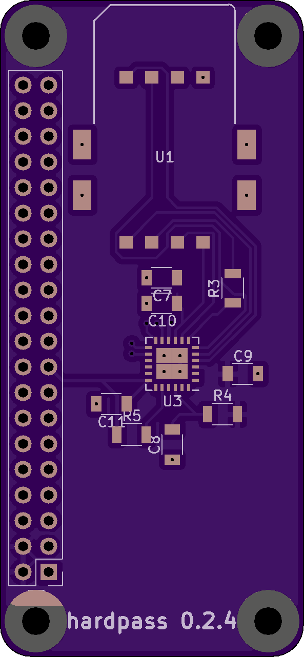
The PCB (files available from GitHub) can be ordered through any of the common PCB manufacturers. For some, you need to export the .kicad_pcb into Gerber files; this can be done with the plot function in pcbnew.
Due to the limited space on the board, order of operations is critical.
Now is a good time to test the PCB with a Pi with a female header installed.
If you need access to the back side of the PCB while it is powered on, install a male header on the Pi, so it is facing the backside. You can then use a 40-wire IDE/PATA cable to connect the Pi to the hardpass PCB. (Warning: do not use the common 80-wire cable - the IDE ground pins (which are not the same as the Pi's ground pins) are shorted together on those!)
Refer to the software setup guide on how to install the components hardpass is made of. You won't be able to (easily) part the Pi from hardpass if you continue here!
This is where you could be finished - unless you want Smart Card support. The order of operations on this board isn't important, just be careful to align the IC correctly. Refer to the Schematic, PCB CAD file and 3d Viewer if you are unsure.
Congratulations, hardware work is done!
**TODO**: case design (laser-cut acryllic front-/backplate?)
**NOTE**: this guide was written for an older version of Raspbian jessie - there have been a lot of changes since then (Raspbian stretch, lite images). **TODO**: needs updating
hardpass runs on the latest Raspbian image from RaspberryPi.org. The Raspberry Pi Foundsation's Installation Guide is very helpful.
Boot up the Pi, set up networking and change the following settings in sudo raspi-config:
Raspbian does not include the SDIO driver necessary for ESP8266-WiFi. Andrew Litt provides a pre-packaged version of the kernel module here. If you want to build the latest version yourself, use this:
git clone https://github.com/al177/esp8089.git
cd esp8089
make
sudo make install
You now should be able to try and connect your Pi to you WiFi through the ESP.
Next, set up the Device Tree Overlay to get the display working with:
sudo -i
echo "i2c-dev" >> /etc/modules
echo "dwc2" >> /etc/modules
exit
**TODO**: systemd tweaking, service file, hardpass repo
Finally, change the password of the pi user!
hardpass relies on pass for its password management. Instructions on installing and configuring pass can be found at the project homepage linked above.
If you decided you want to use a smart card, now is the time to generate (or import) keys on the smart card.
**TODO**: smart card initialisation
Afterwards, refer to pass' documentation again on how to import preexisting passwords using an import script.
Now it is time to switch over from using the command line to using the screen and buttons on the device.
Use sudo systemctl enable hardpass.service to enable hardpass' user interface and reboot.
If you have a look at you host computer's dmesg -w output, you should see hardpass identify itself as a Composite USB device; afterwards, an entry in lsusb should also have appeared. Note that for libcomposite, no Windows driver is available. Refer to the documentation on how to swap drivers **TODO**.
Try to decrypt a password and let hardpass write it into a text editor. Yu can navigate the menu system the following ways: