hue-wheel.pl over UDPLast year, I've made my first and only impulse buy at Ikea: a cheap(-ish) RGB flexible light stip. Immediately, I was immeasurably disappointed: You cannot produce white light with its stupid controller.
hue-wheel.pl over UDP
My patience ran out ten months later, and I set out to replace the on-board microcontroller with an ESP8266. Objectives were:
I've settled on a very simple binary UDP protocol, where one can set the currently displayed colour (and intensity) with a single packet. Defining this protocol was the first item to be tackled. Each packet starts with a uint8_t that defines the type (and therefore the structure of the rest of the packet). Every request is either acknowledged with ACK (0x06), possibly followed by more bytes, or refused with NAK (0x15).
0x00
<ACK> <power> <red> <green> <blue>
0x01 <power>
<ACK>
0x02 <red> <green> <blue>
<ACK> if red+green+blue ≤ 512; <NAK> otherwise.
0x03
0x04 "ssid" <NUL> "psk" <NUL>
0x05 <IP> <CIDR> <GW>
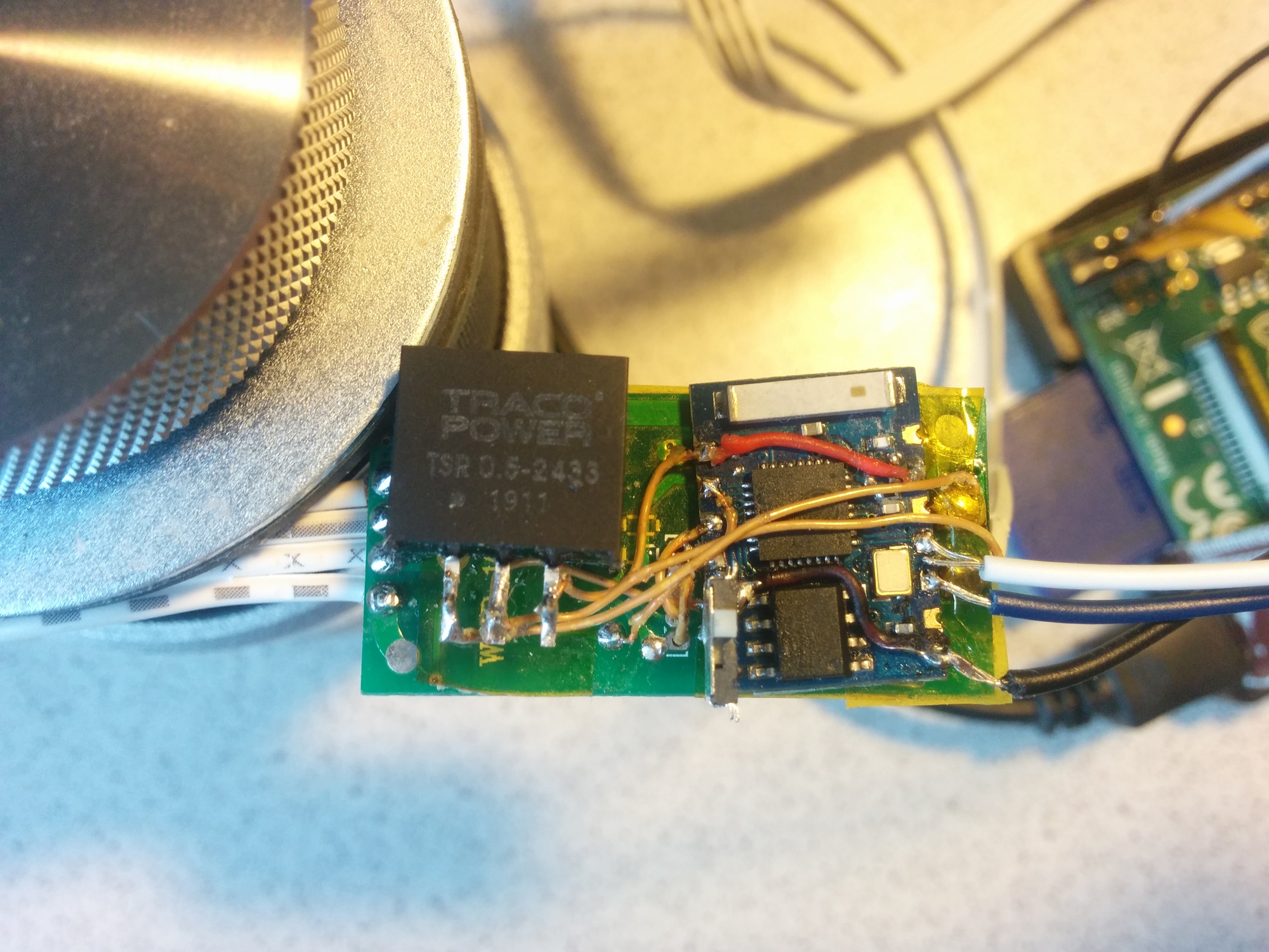
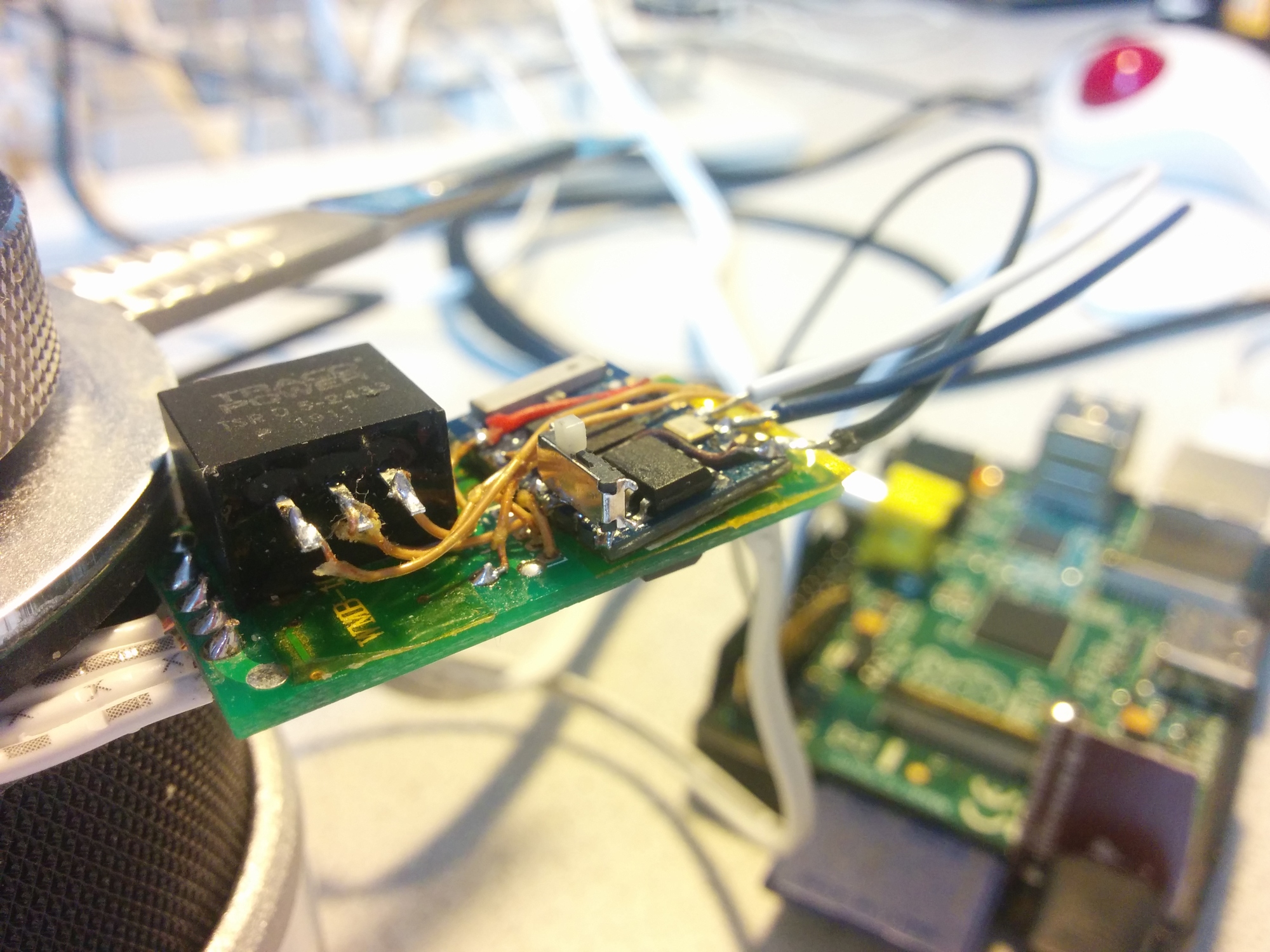
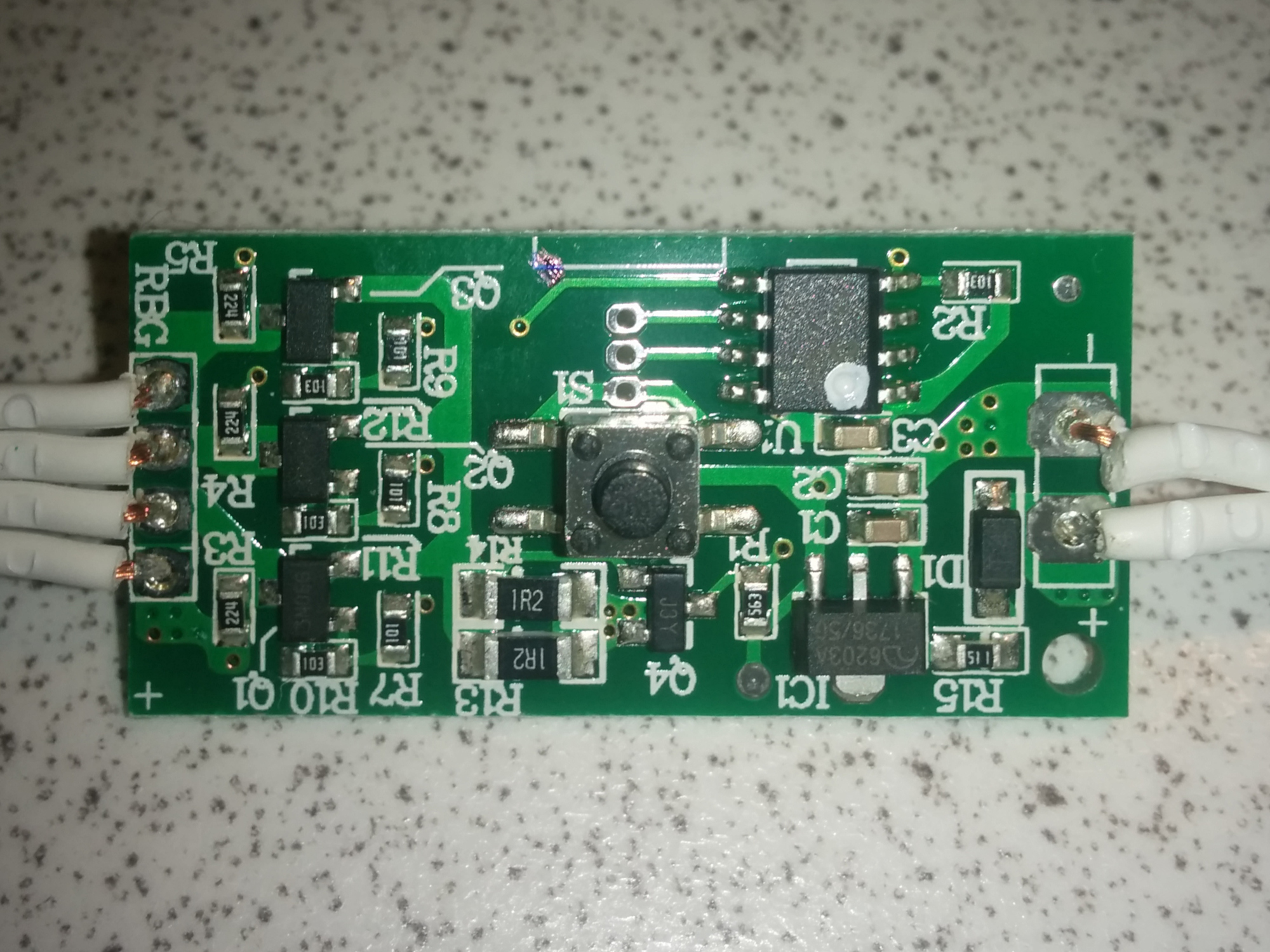
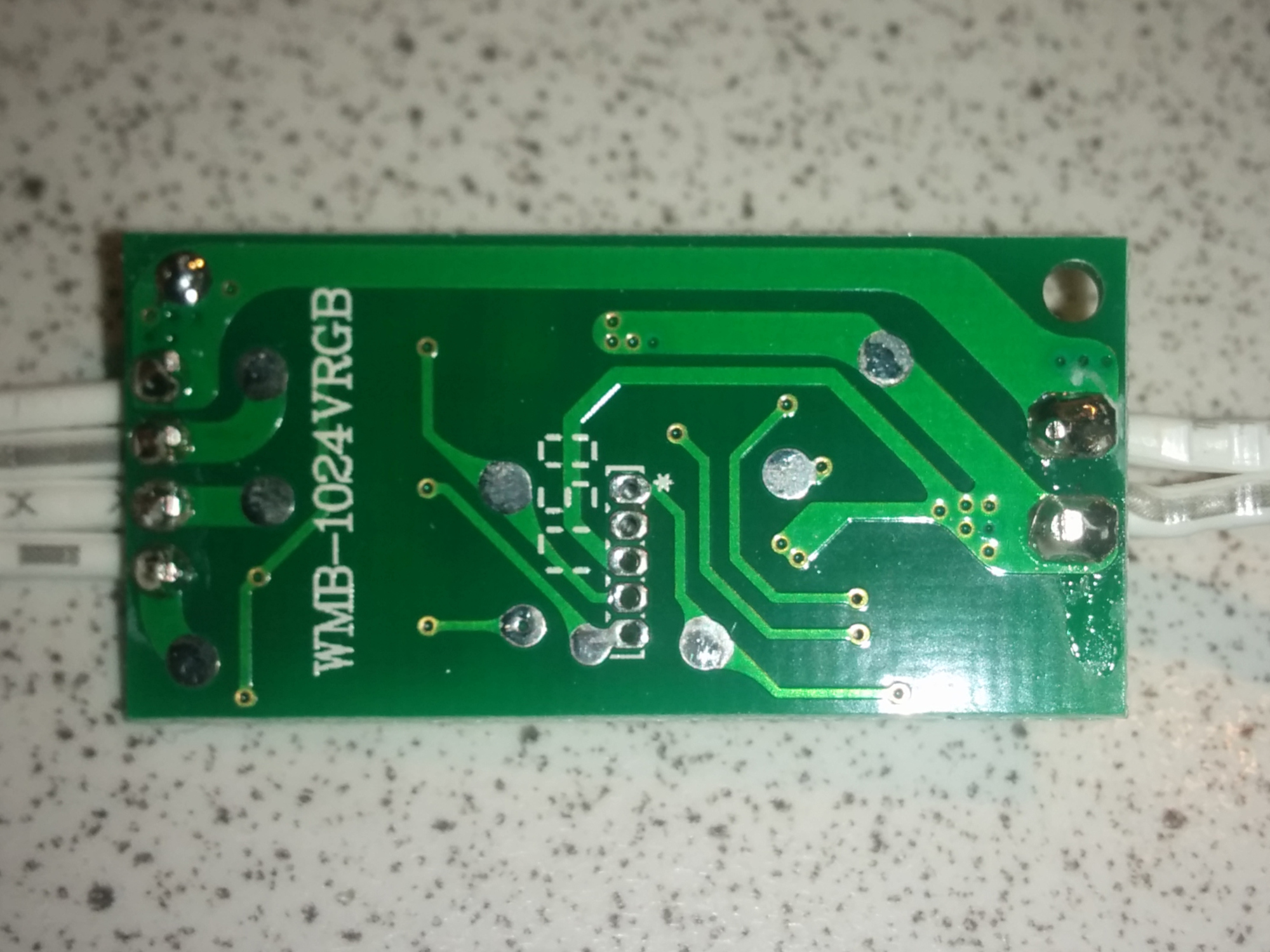
As mentioned at the beginning, using parts at hand was the main factor for deciding the BOM. Therefore, reusing the existing PCB and its MOSFETs was a no-brainer. Initially, I expected to be able to re-use the 5V linear regulator as well (by daisy-chaining a 3v3 LDO), but it (in hindsight obviously) cannot supply enough current for the ESP. Because of this, I purchased a Traco Power TSR-0.5 series switching regulator, which was the cheapest option. From other projects, I have plenty of ESP-03 boards left over.
	+---------+
	| ======= |
vcc	o----,    o
led_r	o    '----o  ch_pd
led_g	o         o
led_b	o         o  rx
gpio15	o-----,   o  tx
	o     |   o
gpio0	o--/.-'---o  gnd
	+---------+
The ESP-03 and regulator were mounted on the back side of the original controller's PCB with double sided- and insulated with Kapton tape. Enamel coated wire then connects the ESP, regulator and test points of the PCB (the wire came from the secondary coil of a cheap wall wart that went kaputt recently).
The insulated wires going to the Raspberry Pi came from a JST-connector terminated cable, which makes it easy to attach to the GPIO header.
The ESP-03 requires gpio15 to be tied to ground and ch_pd pulled high. When gpio0 is pulled low (by a botched-on SPST switch), it enters bootloader mode, which allows flashing new firmware over the serial connection.
Before attempting to open the case of the Ledberg controller, I searched the Internet for pictures of it to reverse some of the required connections. There were none. I've attached my own images and a composite of the copper layers, in case anyone is curious, at the end.
Since—despite owning multiple ESP boards—I've never programmed one (I only used them as a SDIO wifi adapter for the Pi Zero), I used the Arduino IDE and associated Wiring and ESP8266* libraries. Starting from the UDPSendReceive.pde example, adding some analogRead()s was all it took to get up-and-running.
The original controller only illuminated at most two of the three channels, probably to not overload the power supply. I've reimplemented a similar restriction in my firmware: any PWM values exceeding the sum of ⅔ of maximum power are NAKed and discarded. The UDP client will have to make sure to scale values appropriately. Incidentally, a relatively clean white colour can be generated with (1, .5, .5)—so the current limit does not hinder objective №1.
I have not yet bothered implementing any network configuration described in the protocol. I'm sure it'll come back and bite me sooner or later.
(source)
From the onset, I wanted to keep the complexity off the ESP. I've written a few small scripts, in shell and Perl, to set colours or cycle through them.
After figuring out that a 50% green and blue, 100% red channel gives a white, as nice as a non-RGBW chip can produce, all it takes is a shell-oneliner. A beautiful article about simulating colour temperature for 3D rendering contains tables, which PWM values (after colour correction) approximate which light source.
printf '\x02\xFF\x7F\x7f' | nc -u 10.42.0.74 1337
printf '\x02\xFF\x6B\x55' | nc -u 10.42.0.74 1337
printf '\x02\x2F\x10\x00' | nc -u 10.42.0.74 1337

To cycle through some bright colours, I've written a small Perl utility that rotates through the HSV colour space with saturation and value at 1, and the hue incrementing in 1° steps. This is then converted to RGB values, colour corrected and sent by invoking netcat.
(source)
Another simple Perl script, simulating an effect often(?) seen on RGB Gaming equipment. A sinusoidal brightness pattern looks nicer than a linear ramp, I noticed.
(source)
More on the annoying side of the spectrum: select a colour (and intensity) at random each second. It uses Bash's array functionality to select one of three intensity values. Note that only red will access 0xFF, as to not exceed the current limit.
(source)
Unable to find a colour picker GUI, that returns on stdout, I used grabc to just click on a colour palette image in Firefox.
picker.sh
The Free and Open Source Software "AppStore" F-Droid provides a utility called Packet Sender, that can send arbitrary UDP packets. I've configured it to set some predefined colours, and of course on/off packets. To install it, you will need to enable the Archive Repository in F-Droid's settings. I sometimes have problems with the app trying to send packets through a port that is probably in TIME_WAIT state; restarting the app usually helps.

This should™ be relatively easy: coax VLC into spitting out mean screen colour and pipe it into netcat. Apparently, VLC media player did include an option for this in the past, but it looks like it was removed after 2.2.
A sort-of VU meter where brightness corresponds to current loudness peak should be doable as well: Read the current levels from PulseAudio, massage the values into a brightness to send over UDP, and Bob's your uncle!
When this project was discussed on Hackaday, some questions came up, which I'll provide my point of view to here.
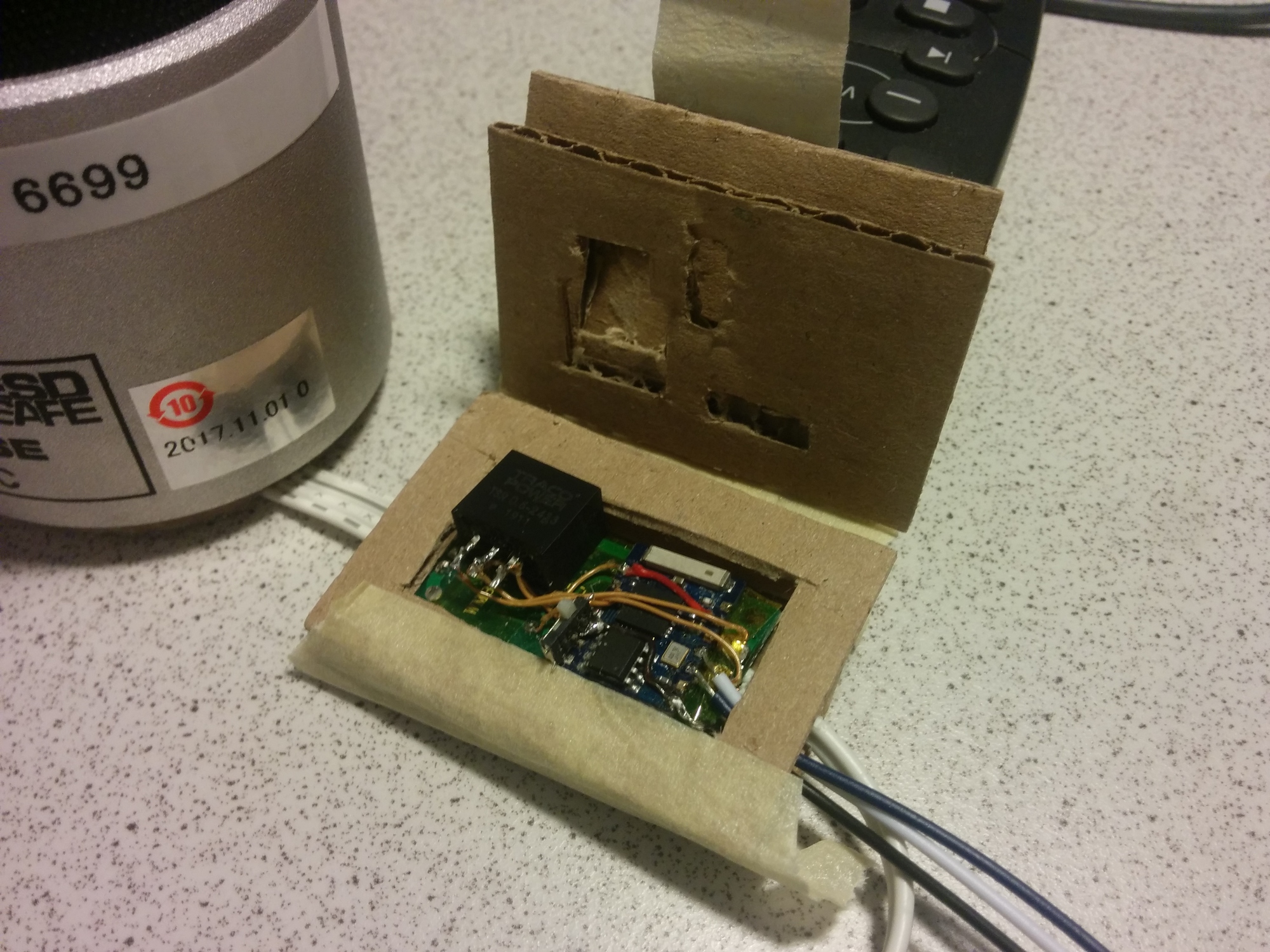
Due to the height of the DC/DC converter, I couldn't reuse the existing case. To again only use materials in my apartment, I emulated the layered acrylic case designs, but made out of corrugated cardboard. It looks jank, but doesn't take hours to design and print. The final layer is hinged with painter's tape to access the bootloader/programming switch. The contraption is stashed out of view behind my desk.
To find out what on the board I can reuse, and where to tack on my ESP, I took pictures of both sides of the PCB, and composited them in the GIMP. The new Handle Transform Tool in 2.10, in combination with some guide lines made straightening and aligning both images quick and easy. Then, I used the Scissor Select Tool to trace and isolate the bottom copper layer; shifted the Hue by 180° and set its opacity to ~50% and superimposed in on top of the component-side image. I also copy-pasted the pinout from the PIC's datasheet on top of the MCU. It's a PIC12F1572, if you were wondering. Finally, I looked for probe points on the bottom side and marked them with the Paintbrush. All in all, it took me probably around 10 minutes, and I am not an expert GIMP user.
A note on the case: Wow, that think is tough! It is glued at the seam; the way to open it up is to carve a hole through the side, then stick a knife in and rotate it to force the glue to crack.
Click on the images below for a hi-res version; or look in the repository for the original .xcf, where you can play around with the layers.

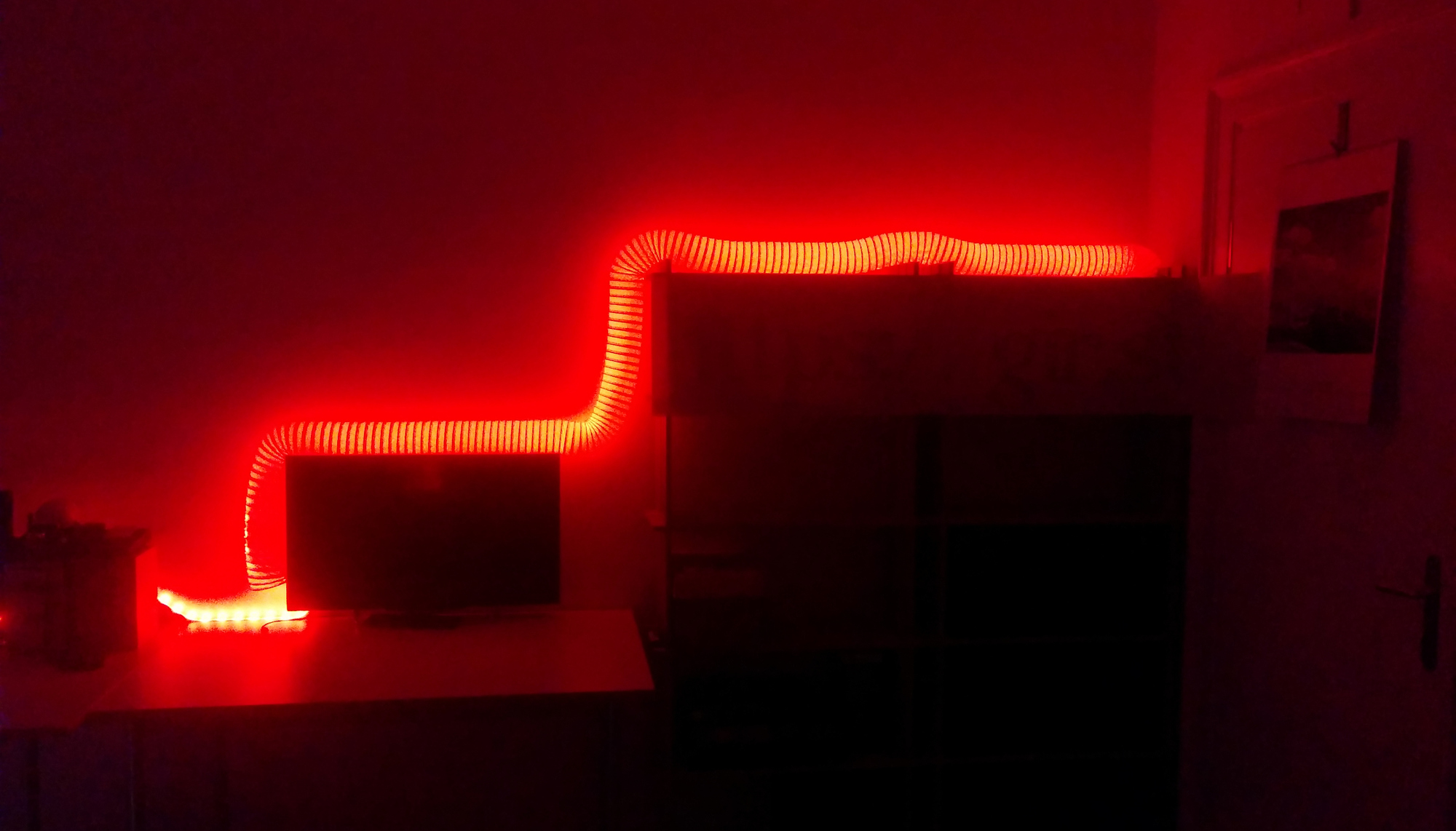
As you might have noticed on the pictures of my light strip, it is covered in a PVC dryer hose. I think I've copied that from someone attending 35c3, but I cannot remember exactly. It does look neat though, in my opinion! :D
The banner below it was generated with banner(6) – unchanged since 1979. Its primary purpose is to hide the mess in my storage rack.
Usually, I'd just link to one of the numerous well-written other blog posts for a triviality like flashing firmware onto an ESP module. But my unusual setup did require some extra care, which I'll document for your enjoyment (and definitely not my own future reference :P).
I installed the Arduino IDE on my desktop PC. However, I did not find my USB UART dongle; so I decided on flashing the firmware via an original generation Raspberry Pi B and Espressif's esptool (no installation required; just git clone it somewhere). However, my Pi lives in a different network than my Desktop. OpenSSH has this very neat feature called "ProxyJump." It provides a tunnel through an intermediate device straight through to your target. No need to shell into the intermediate node, and manually issue another ssh command there. In my case, the intermediate device was my router: an old EEEPC-701 with a taped-on LTE modem and WLAN adapter (It runs Void and NetworkManager/ModemManager in "share connection mode").
Every cycle of the development looked like this:
*.ino file.
scp -oProxyJump=user@router.local Udp.ino.generic.bin root@raspberry.local:firmware.bin (you'll be prompted for authentication to the JumpHost, then to the target host).
ssh -J user@rooter.local root@raspberry.local /root/esptool.py write_flash 0x0 /root/firmware.bin
watch 'ip n|grep $MAC_OF_ESP' is useful. The MAC address can be obtained with ./esptool.py read_mac while in bootloader mode.
If you're familiar with the Graphics Interchange Format, you'll no doubt be aware of its 256 colour limitation. But how do these GIFs look so much better?
– Because you can actually switch palettes whenever you want. For the first image I split the video into frames with ffmpeg (ffmpeg -i in.mp4 -vf scale=480:-1:flags=lanczos,fps=10 frames/ffout%03d.png), manually partitioned them by what looks right (6 buckets à 21 frames), then generated six animated gifs with one palette each (convert -loop 0 frames/ffout*.png output-1.gif). They were then merged with convert output-*.gif huewheel.gif. This of course increases the file size, but was (to me) an appropriate trade off. BTW, ffmpeg can even automatically generate gifs with a palette per frame.